✓ Do
- Check resistance before, during and after installation (use digital ohm meter). See page 13 for more information.
- Use circuit fault detector throughout installation. Leave it connected until the entire installation is complete and tested.
- Ensure floor surface is dust free.
- Install finished flooring as soon as possible after heating system is installed.
- Install & provide power in accordance with your local electrical codes and standards.
- Register your heating system at cosyfloor.ca/warranties to retain your lifetime warranty.
- Ensure the cable is completely encapsulated in thinset mortar or self-leveling cement prior to installing flooring.
✕ Don’t
- Forget to install thermostat floor sensor wire included with thermostat.
- Install heating cables closer than 6″ to toilet flange.
- Scrape, sand, or sever wires in any way.
- Bang trowel or other sharp object on floor.
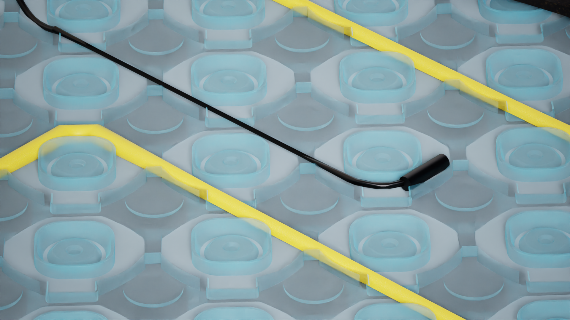
- Install cables closer than 2″ to each other, cross cables, thermostat sensor, or black cold connection cable.
- Use knife to clean grout lines.
- Open splices, cut or modify cable in any way.
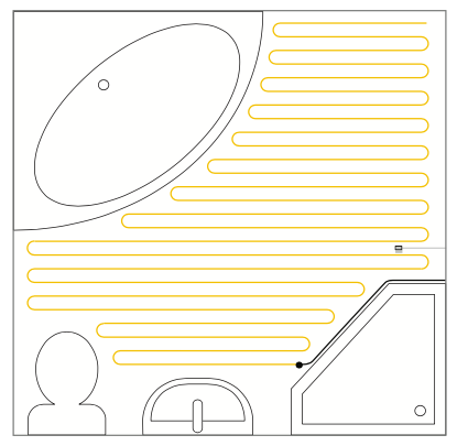
- Measure floor area to be heated & determine square footage of heating cable and membrane needed. Order the correct size. Do not install heating cables under any fixed furniture (e.g., vanity units).
- Be sure to leave area close to toilet flange free of heating cables (6” radius). It is recommended that heating cables are installed 4” away from all walls.
- Standard spacing of 3” is recommended for most areas. For high heat loss areas such as floor over unheated crawl spaces or non-insulated concrete slabs use cable spacing of 2”.
- The yellow heating cable must NEVER cross at any point — this includes the thermostat sensor probe wire.
- Make sure the thermostat floor sensor is able to be installed midway between 2 heating cables without crossing them.
- Plan for your floor sensor to be 12” away from any heating or cooling registers and avoid areas where forced air ductwork below the floor may affect the sensor. Also ensure the floor sensor will not be in an area covered by a bathmat or area rug.
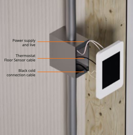
- A suitable power supply to a 1-gang deep electrical box should be installed and mounted approximately 60″ from the floor. This should be in the same room that is being heated and should be situated on an interior wall.
- Install a conduit running from the floor to the thermostat box. Some jurisdictions may require a separate conduit for the low-voltage thermostat floor sensor cable.
- Run a pull wire or sturdy string from the 1-gang deep electrical box down through the roughed-in conduits. This is to facilitate the pulling of the black cold connection cable and floor sensor wires through the conduit during installation when the wall has already been finished.
Watchpoint
The installation must be performed in accordance with all National and Local Building & Electrical Codes and any local amendments. Turn off the electrical supply to avoid risk of electric shock.
- Ensure that the subfloor does not have flex or movement.
- Ensure subfloor is dust free.
| Substrate | Preparation |
|---|---|
| Cement |
Cement slab must be compact and structurally sound. Cracks and fissures in the cement slab need to present only longitudinal movement. Debris, dust, wax, grease, and oil residue must be removed or abraded/scored to create better bond to the thinset. |
| Wood |
Wood subfloor needs to be properly fastened and secured to the framing structure. Wood subfloor needs to be clean of dust, residue, wax, oil, and grease. Wood subfloor should be levelled before installation. Remove all exposed nails, screws, fasteners, and debris. |
-
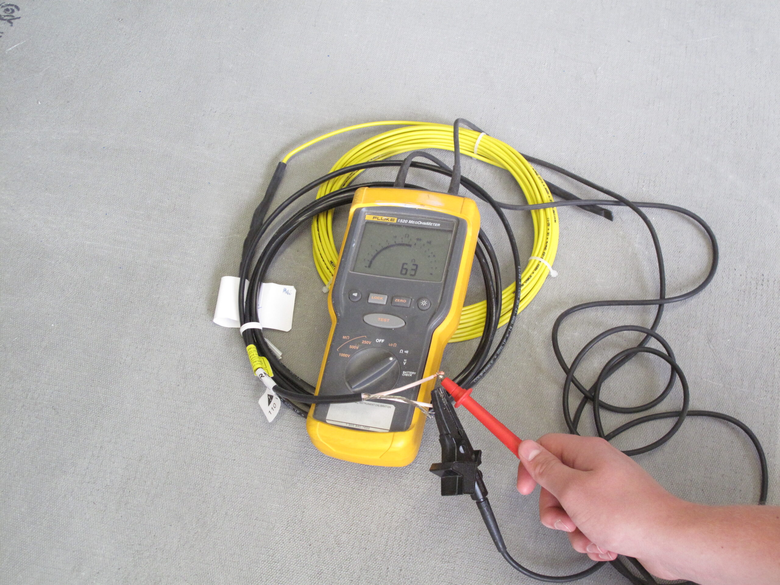
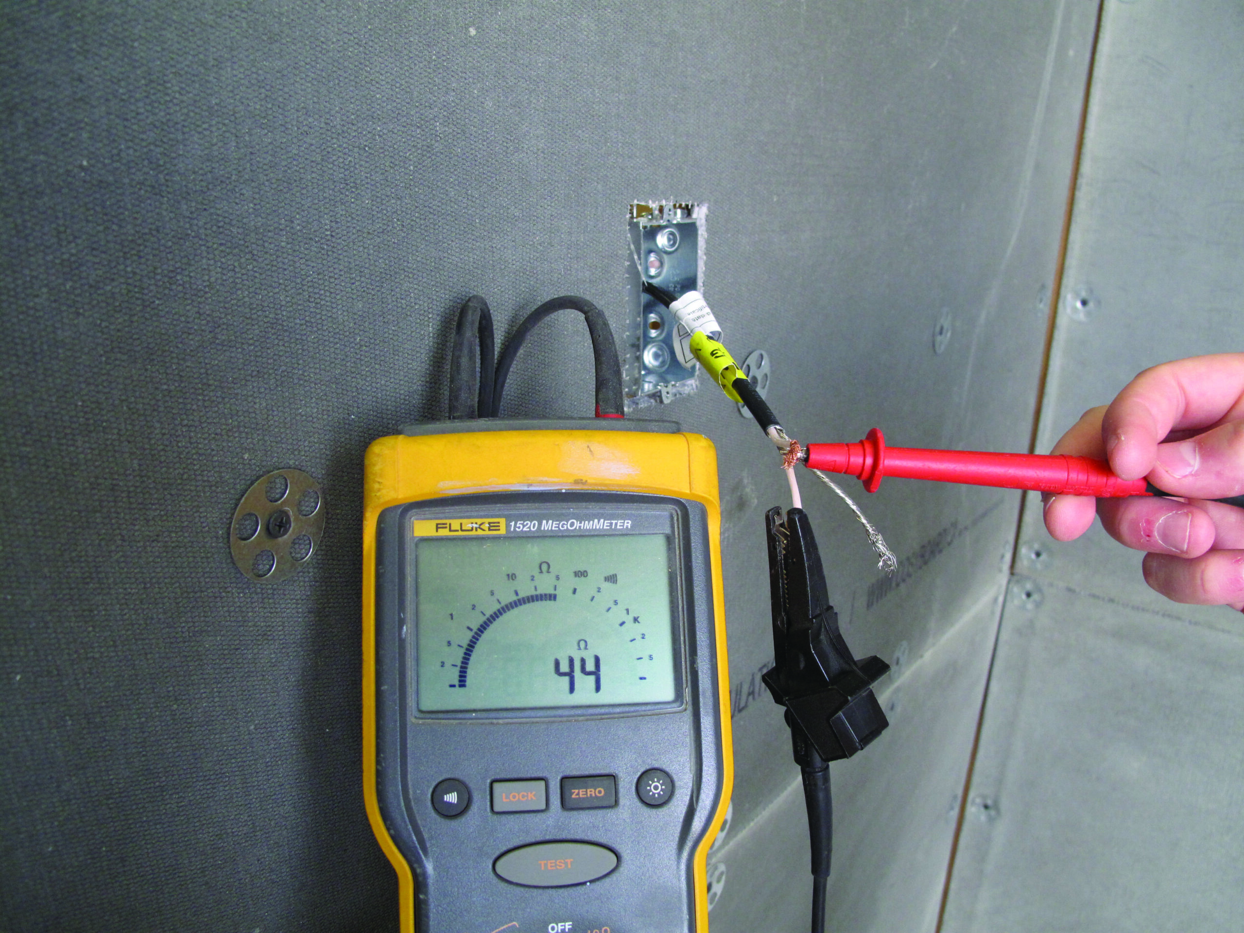
Locate the end of the black cold connection cable and using a digital ohm meter measure the resistance as follows:
- Between heating conductor 1 (insulated wire) and heating conductor 2 (insulated wire) — This reading should be within 5% of the stated ohm reading from cable tag.
- Between heating conductor 1 (insulated wire) and ground (uninsulated wire)
- Between heating conductor 2 (insulated wire) and ground (uninsulated wire)
- Important: These should have no reading or .OL (open load). If you have an ohm reading at this point, STOP AND DO NOT CONTINUE WITH INSTALLATION. Measure Ohm reading for thermostat floor sensor. The thermostat floor sensor should read between 8 and 12 kohm.
- Measure ohm reading for thermostat floor sensor — this reading should be between 8 and 12 kohm.
- Record all four readings on page 12 of this installation guide.
- Connect the circuit fault detector to the heating cable. This device is provided to ensure that you leave it connected throughout the entire installation.
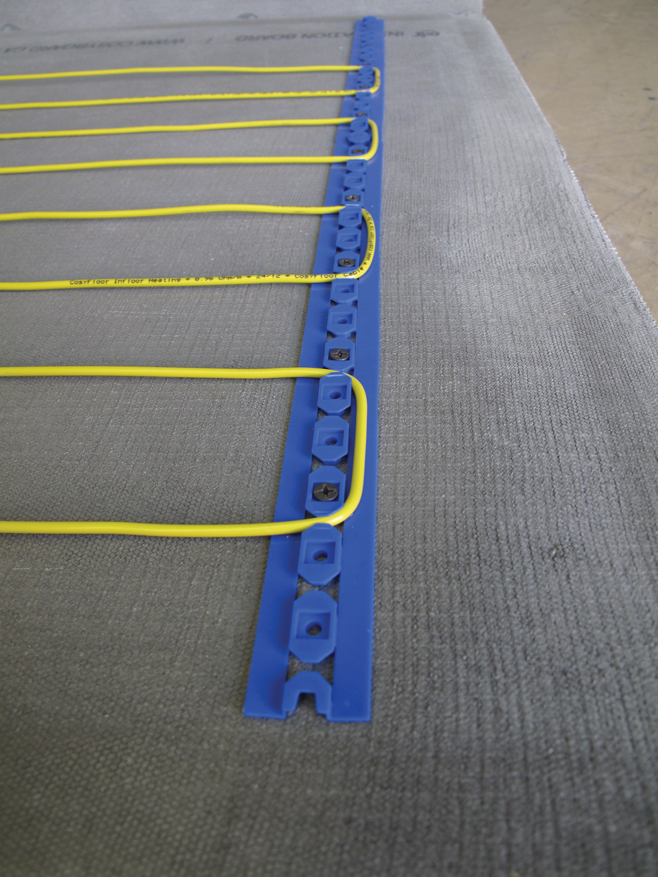
Secure fixing strips to the floor at both ends of the room where the cables will be fastened.
Wood subfloor: Screw fixing strips directly to subfloor.
Concrete subfloor: Use contact adhesive such as 3M 90 or similar.
For installations with curved walls, cut the fixing strips as needed and install with additional fasteners as needed.
After securing the fixing strips to the ends of the room, install additional fixing strips in parallel rows at 5’ intervals. These strips should span the entire area where you plan to lay the yellow heating cable, ensuring the yellow heating cable is securely held in its intended pattern throughout the room.
- Securely attach the pull wire from Step 1 that extends out of the conduit near the floor to the black cold connection cable end. Pull the pull wire back up through the conduit, guiding the black cable up to the 1-gang deep electrical box.
- Leave all cable tags on cable and ensure they remain in electrical junction box.
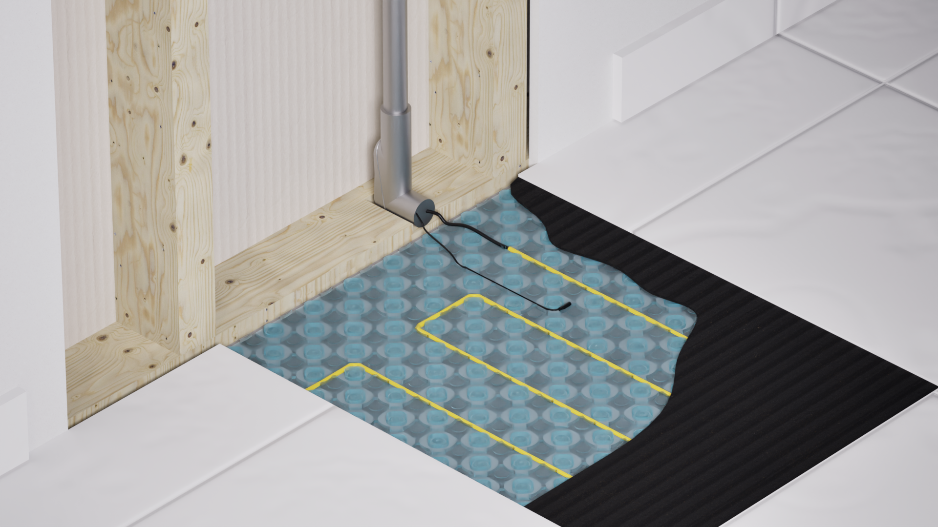
- It is recommended to lay the spliced connection of the black cold connection cable and yellow heating cable in the expansion gap (the gap between the floor and the wall) to be covered by baseboard or trim.
- DO NOT BEND THE CONNECTION BETWEEN BLACK COLD LEAD AND YELLOW HEATING CABLE.
- NEVER ALLOW YELLOW HEATING CABLE TO GO UP WALL OR INTO CONDUIT.
- Starting at one end of the room, string the heating wires between the fixing strips, clipping them in every 3”. Depending on your application, 2”–4” spacing is acceptable.
- Use provided fastening tape to hold wires to the floor as needed between rows of fixing strips.
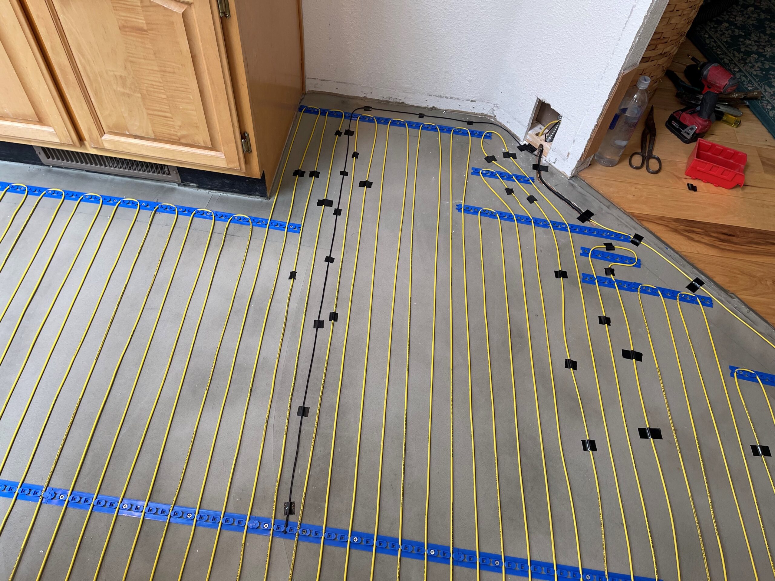
- Position end of sensor probe in the exact center between 2 runs of yellow heating cable.
- Important: Lay your floor sensor 12” away from any heating or cooling register and avoid areas where forced air ductwork below the floor may affect the sensor. Ensure the floor sensor will not be in an area covered by a bathmat or area rug.
- Fasten floor sensor with the fastening tape provided, if needed.
- Feed floor sensor wire up through your conduit to the electrical box.
-
Locate the end of the black cold connection cable and using a digital ohm meter measure the resistance as follows:
- Between heating conductor 1 (insulated wire) and heating conductor 2 (insulated wire) — This reading should be within 5% of the stated ohm reading from cable tag.
- Between heating conductor 1 (insulated wire) and ground (uninsulated wire)
- Between heating conductor 2 (insulated wire) and ground (uninsulated wire)
- Important: These should have no reading or .OL (open load). If you have an ohm reading at this point, STOP AND DO NOT CONTINUE WITH INSTALLATION. Measure Ohm reading for thermostat floor sensor. The thermostat floor sensor should read between 8 and 12 kohm.
- Measure ohm reading for thermostat floor sensor — this reading should be between 8 and 12 kohm.
- Record all four readings on page 12 of this installation guide.
- Connect the circuit fault detector to the heating cable. This device is provided to ensure that you leave it connected throughout the entire installation.
- Keep foot traffic & general construction to a minimum until tile flooring is installed.
- DO NOT use a knife to clean grout lines.
- DO NOT have floor heat on during floor install.
- The membrane does NOT eliminate the need for expansion joints including perimeter joints within the tiled surface. Expansion joints must be installed in accordance with industry standards and norms. (TCNA EJ171 and TTMAC 301 MJ).
- Thinset may be flat troweled one day and floor finish installed the next day if preferred.
- Cover floor and heating cables with thinset mortar or self-leveling concrete compound in accordance with manufacturer’s instructions. Ensure that all cavities between cables and membrane or fixing strips are filled.
- Use a trowel float or the flat side of a notched trowel to gently spread, ensuring full coverage of the heating cables; be careful not to damage the heating cables beneath.
- Ensure that the thermostat floor sensor is entirely encased in thinset mortar. Ensure that no part of the sensor comes in direct contact with your tile or flooring material.
- Before setting each tile, back butter it with thinset mortar. This ensures maximum coverage and adhesion. Once the tiles are set, allow the thinset to cure completely, following the mortar manufacturer’s recommendations.
- Finally, fill the grout joints and carefully remove any excess grout from all surfaces, including the tile edges, using the edge of a float. Allow the grout to cure as per its manufacturer’s guidelines. Remember that grout can be a corrosive product, so work carefully and clean thoroughly.
Locate the end of the black cold connection cable and using a digital ohm meter measure the resistance as follows:
- Between heating conductor 1 (insulated wire) and heating conductor 2 (insulated wire) — This reading should be within 5% of the stated ohm reading from cable tag. —
- Between heating conductor 1 (insulated wire) and ground (uninsulated wire)
- Between heating conductor 2 (insulated wire) and ground (uninsulated wire)
- Measure ohm reading for thermostat floor sensor. — This reading should be between 8 and 12 kohm. —
Record all four readings on page 12 of this installation guide.
Connect the circuit fault detector to the heating cable. This device is provided to ensure that you leave it connected throughout the entire installation.
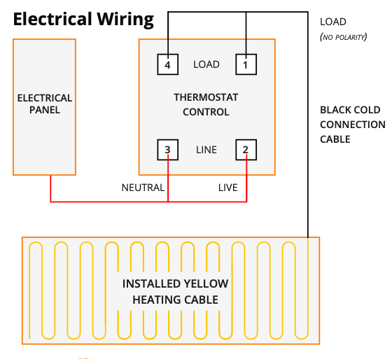
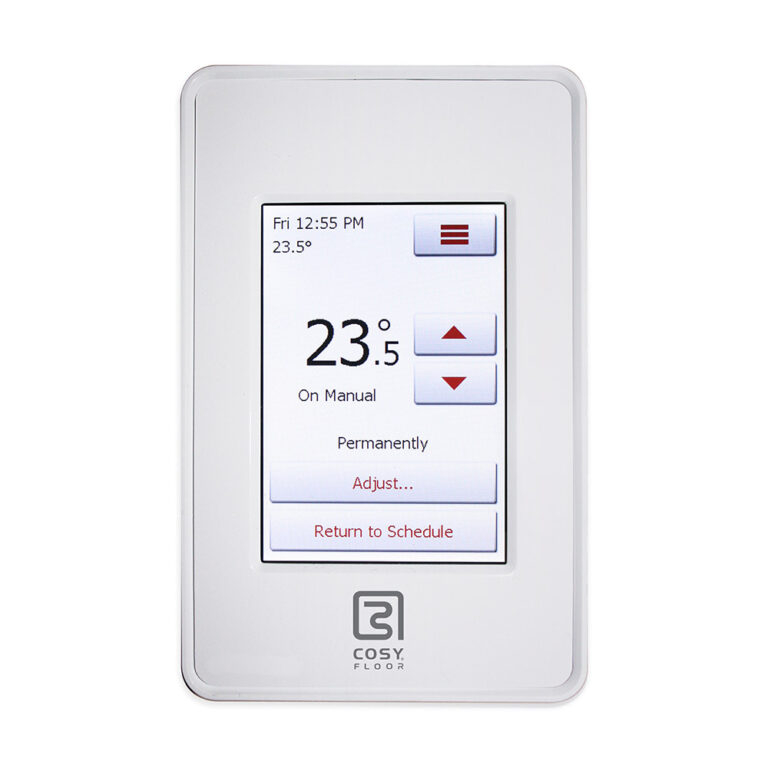
Install thermostat in accordance with thermostat instructions.
Find your CosyFloor Thermostat instructions here:

Once the installation is complete, upload warranty data at
www.cosyfloor.ca/warranties/
Upon registration of warranty, CosyFloor will email the owner with warranty registration confirmation.
Provide the following to the homeowner:
- This Installation Guide
- Thermostat Programming Instructions
- Heating cable test readings taken during installation
- Layout Drawing
Remind the homeowner of the location of the heat sensor, and the importance of never covering the sensor with a bathmat or anything else that may cause the sensor to give a false reading.
| Issue | Resolution |
|---|---|
| Thermostat screen is blank |
|
| Heating Cable resistance does not correspond with measurement on CosyFloor factory test certificate |
|
| Heating Cable is not heating up, and thermostat display says “GFI” |
|
Comprehensive Lifetime Warranty
- Complete peace of mind covering all materials and labour for your full flooring project.
- 100% coverage – no depreciated cost methods.
- Lifetime, for the original homeowner.
As in-floor heating specialists with 20 years of experience manufacturing and supplying in-floor heating systems across North America, we know the importance of our warranty commitment to installers and end-users.
– All thermostats carry a 3-year warranty.
– This warranty applies for all in-floor heating systems installed after January 1, 2025.
These resistance tests are crucial for ensuring the proper functionality and safety of your CosyFloor heating system. Please follow these instructions carefully. If any test indicates a problem, stop installation immediately and do not proceed.
Stage 1: Test Before Beginning Installation
Purpose: To detect any manufacturing defects or damage to the yellow heating cable before installation.
Stage 2: Test After Cable Layout, Before Floor Installation
Purpose: To ensure the yellow heating cable has not been damaged during the layout of the CosyFloor System.
Stage 3: Test After Floor Installation is Complete
Purpose: To confirm the yellow heating cable remains undamaged after the final floor covering has been installed.
Between heating conductor 1 (insulated wire) and heating conductor 2 (insulated wire)
- Touch one probe of the multimeter to black cold connection cable 1.
- Touch the other probe of the multimeter to black cold connection cable 2.
- Observe the multimeter display and record the reading on your form.
Between heating conductor 1 (insulated wire) and ground (uninsulated wire)
- Touch one probe of the multimeter to the yellow heating cable ground braid.
- Touch the other probe of the multimeter to black cold connection cable 1.
- Observe the multimeter display and record the reading on your form.
Between heating conductor 2 (insulated wire) and ground (uninsulated wire)
- Touch one probe of the multimeter to the yellow heating cable ground braid.
- Touch the other probe of the multimeter to black cold connection cable 2.
- Observe the multimeter display and record the reading on your form.
Thermostat floor sensor ohm reading:
- Touch one probe of the multimeter to one of the thermostat floor sensor wires.
- Touch the other probe of the multimeter to the other thermostat floor sensor wire.
- Observe the multimeter display and record the reading on your form.